Overview
|
The goal of the Lunar Sample Retrieval System (LSRS) is to deploy upon landing, detect and move to a designated site, and collect 10 mL of simulated lunar ice |
Mission plan
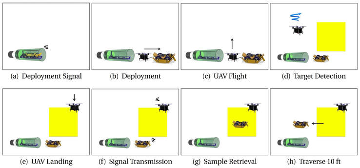
MISSION STEPS
cOMPONENTS
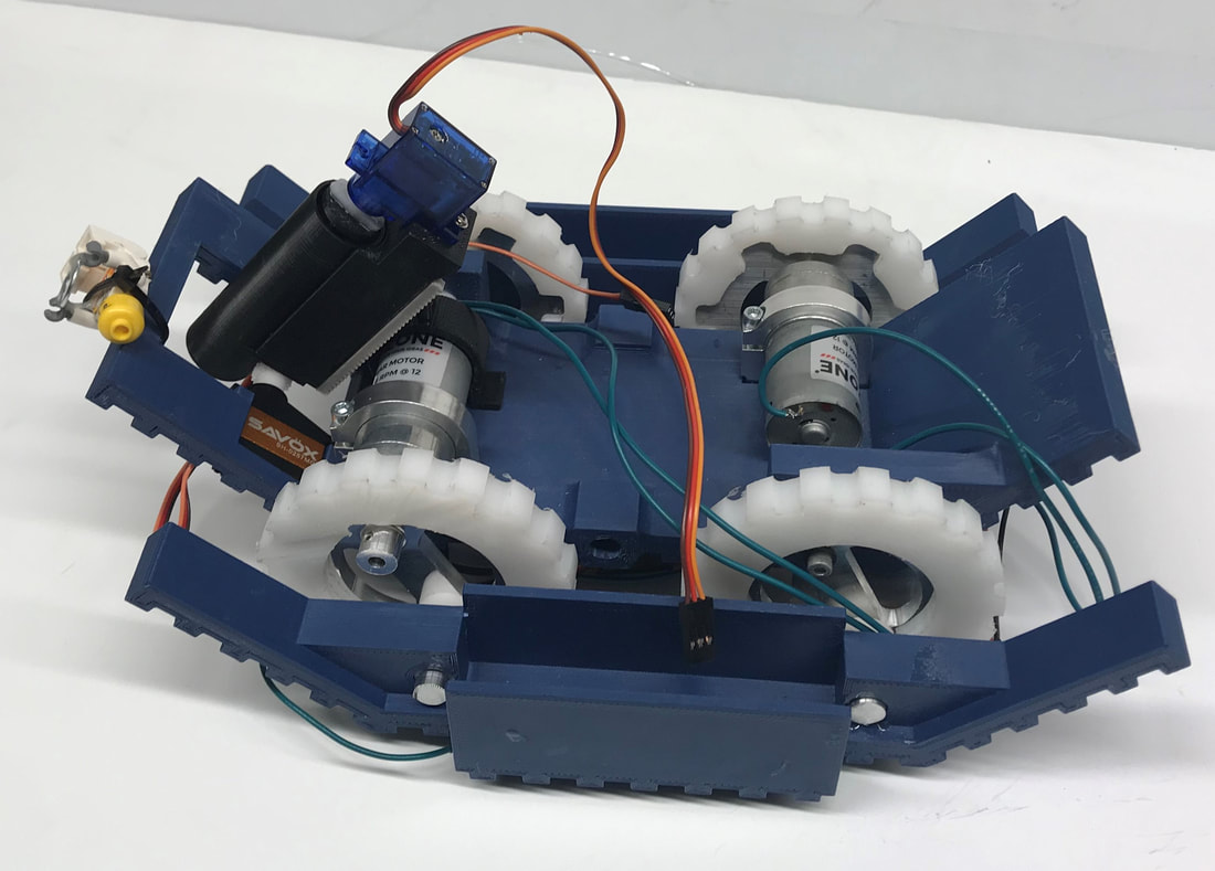
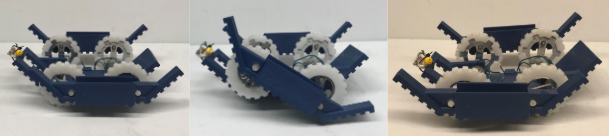
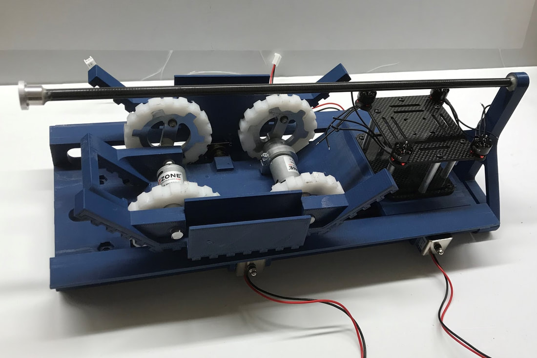
rOVER vEHICLEThe function of the rover is to traverse to the "recovery area" and then extract 10 mL of simulated lunar ice. The rover links move in an eccentric motion relative to the body. Due to this, traversing rough terrain and inclines becomes easier. The center of gravity to remain constant along the horizontal axis. The body, links, and wheels were all 3D printed with ASA plastic. The hubs were lathed from aluminum.
|
|
|
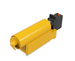
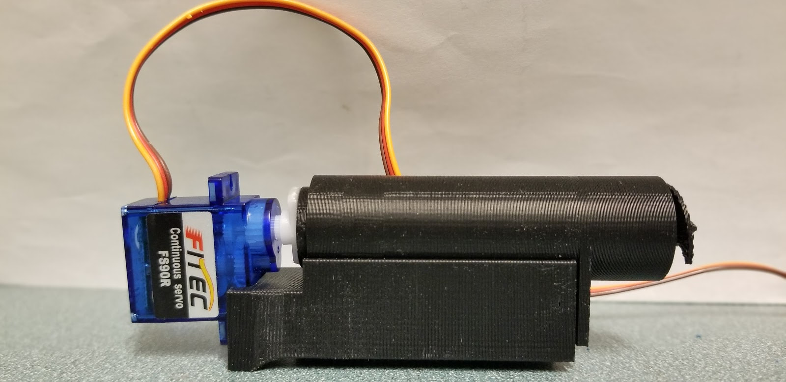
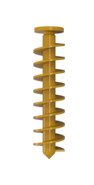
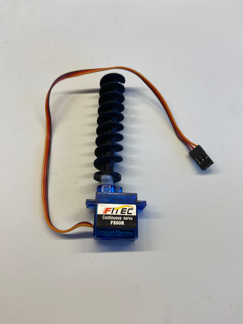
Sample CollectionThe sample is collected by an Archimedes screw. The screw feeds into a box that holds the collected sample. The screw, casing, and collection box were all 3D printed out of ASA plastic. A servo is attached to the screw in order to rotate it, allowing the material to travel up the screw and into the collection box.
|
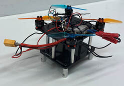
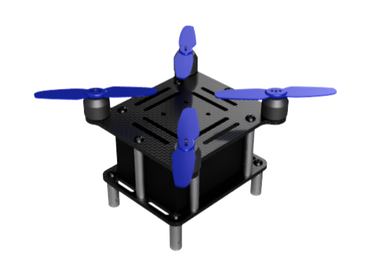
UAV StructureThe UAV decks are machined from carbon fiber. The decks are separated by aluminum rods. On the bottom are aluminum struts that have holes in order to be fastened into the retention system. The UAV uses four props to generate the lift for the 19.5 oz system.
|
|

|
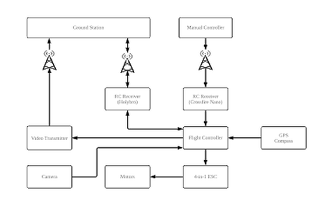
CONNECTION DIAGRAM
|
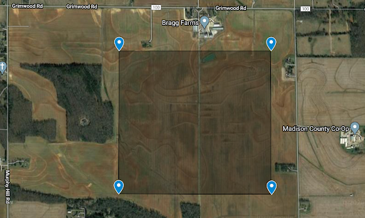
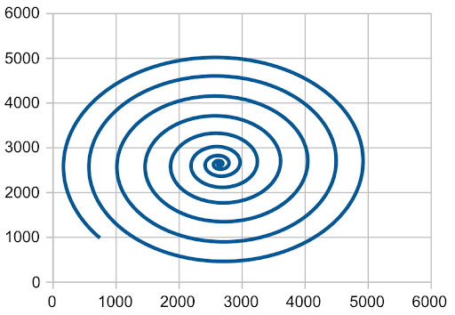
Target DetectionWith a ten minute flight window, the search path for the recovery site must be optimized. GPS coordinates of the launch site are used to delineate the searchable area. If the launch vehicle lands outside the GPS coordinates, the UAV will first fly to the outside perimeter of the field. Then, the UAV will employ an inward spiral search pattern until the recovery site is found. A program was developed using geometric features, color contrasting, and boundary conditions to detect the recovery site. Then the micro controller relays the info to a ground station, that then sends coordinates to the rover.
|
Deployment sequence1. The nose cone and fore bulkhead deploy from a black powder charge upon descent at an altitude of 400 ft.
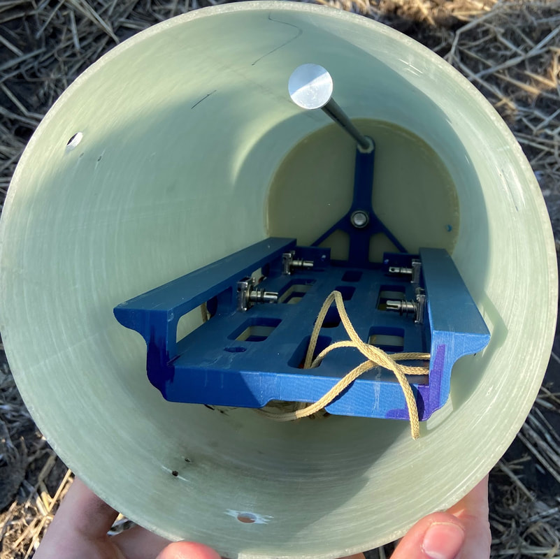
2. The sled system is connected to a bearing that is free to rotate axially once the fore bulkhead is removed. Once the payload bay lands, despite its landing orientation, gravity will cause the sled to reach equilibrium at the bottom of tube. 3. Once the sled is oriented, a signal is sent to release the spring loaded solenoid pegs from the rover and UAV sled that prevent them from moving linearly. As the rover climbs out of the payload bay, it drags the UAV sled behind it until they clear the payload tubing. 4. Both the UAV and rover are unconstrained and able to complete mission. |
The rover and the UAV configuration in the system
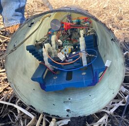
System orienting upon landing
|
An animation of the ease of assembling and disassembling the system in the payload bay
|
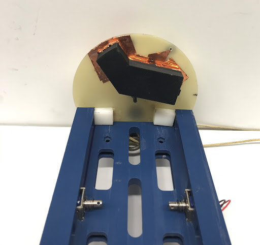
RetentionIt is essential that the system is fully constrained during flight. The system is enclosed in the payload bay during ascent. The aft bulkhead is fixed in the payload bay. To prevent linear motion, the main sled is screwed into rails that are attached via a bearing to the secured aft bulkhead. Both the rover and UAV are secured to the main sled by spring loaded pegs controlled by solenoids. To prevent rotation during flight, the fore bulkhead contains two blocks that prevent the main sled from rotation.
|